General
Cofferdams
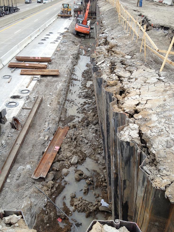
Steel sheet piling may permanent, temporary, or temporary left in place, meaning the sheeting was designed to support earth pressures during staged construction, and removal of the sheeting may be detrimental to permanent structures. Sheeting may also be part of a cofferdam, along with other structural components such as bracing, struts, walers, tie backs, and other related structural components act to create a water tight seal, as to construct substructure elements in the dry. Steel sheeting consists of new or used continuous interlock-type steel sections including connections and corner pieces. Steel sheet piling can resist loads via cantilever capacity, or in combination with bracing such as walers and struts.
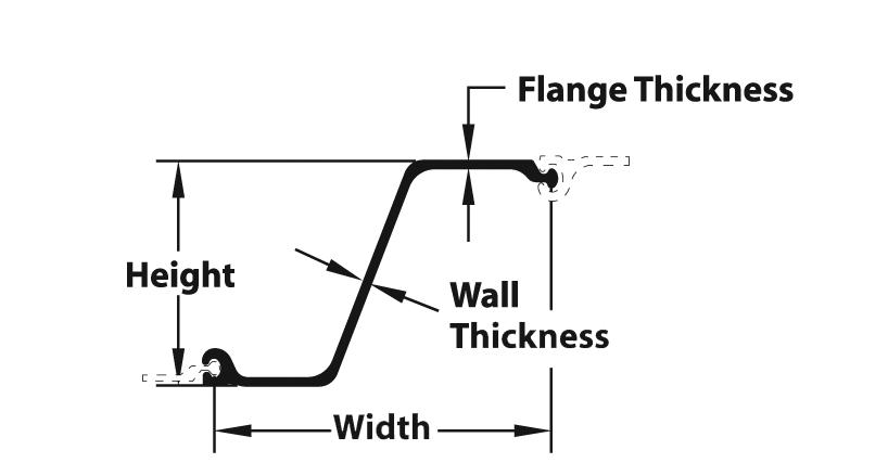
Used steel sheet piling must be in good condition, and its use must be approved by the Engineer prior to driving. The most common steel sheet piling shapes are the PZC types. For example, for a PZC-27 section, the P stands for “pile” the Z is for the “type or shape”, and 27 represents the unit weight per ft2 of material.
Materials
Permanent Sheet Piling
Permanent steel sheet piling details will be included in the contract plans, and will be driven to the penetration elevation called for on the contract plans. The permanent steel sheet piling minimum nominal section modulus, material grade, and all other pertinent information will be shown on the plans.
Permanent steel sheet piling shall be furnished with suitable connections and corner pieces. The inside face is to be located along the footing outline. Cold rolled sheeting will be permitted as long as the sheeting has an equivalent sectional modulus that meets the minimum requirements.
The basis for payment is square foot, based on the full length from plan cutoff to plan penetration.
Temporary Steel Sheet Piling – Temporary Steel Sheet Piling Left In Place
Temporary steel sheet piling details will not be included on the contract plans, other than general limits, locations, and cut off elevations shown in plan and section views typically as part of staged construction. The Contractor is responsible for designing, providing, installing, maintaining and removing temporary steel sheet piling, or cutting off temporary steel sheet piling left in place to the elevations as shown on the plans. Sheeting may be driven to the penetration as determined by the Contractor’s approved design unless otherwise noted by the design plans (i.e., the plans may specify a penetration depth regardless of the design).
The area measured for payment is based on the area of earth retention, and does not include the amount needed for the toe. Vertical dimensions shall be based on the difference in ground elevations at the sheeting line, or planned foundation excavation limits at the sheeting line, whichever is less. This line typically extends from ground line on the earth pressure side, to the bottom of the excavation on the staged construction side unless other limits are designated. If retaining earth on both sides of the same steel sheet piling during different construction stages, the quantity and basis of payment will be based on the stage requiring the largest area of earth retention, not the sum of the areas for each stage.
Temporary steel sheet piling shall have a minimum nominal section modulus of 18.1 in3/ft of wall,when retaining traffic loads or adjacent to traffic. The Contractor’s plans shall show the required embedment depths, steel material grades, connection and weld details, along with required bracing, walers, tie backs and other related structural components.
The basis of payment is square foot, based on all areas retained soil, including cut slopes from the excavation limits to existing ground.
Cofferdams – Cofferdams Left In Place
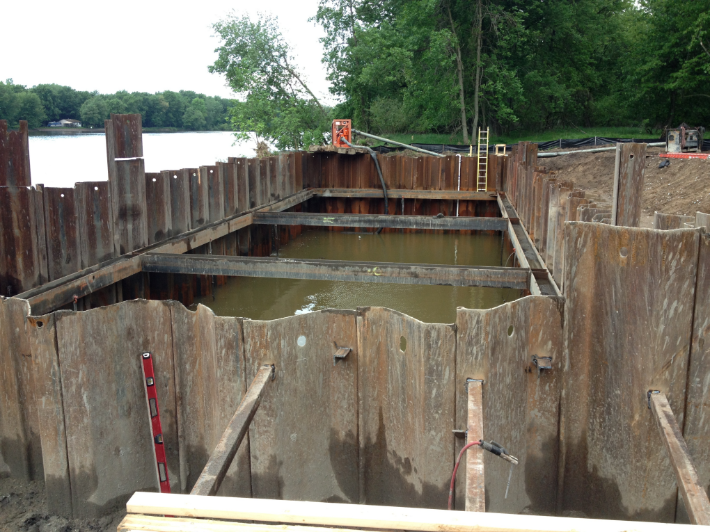
A cofferdam is a substantially watertight enclosure consisting of steel sheet piling and structural bracing components which will permit substructure construction in waterways, or other areas where the construction must be isolated from the surroundings. Steel sheet piling is part of the overall structural system resisting earth and hydraulic pressures. Some cofferdams may require bracing, struts, walers, tie backs and dead men to maintain acceptable stresses on the members, while allowing no more than 2” of deflection at the top of the sheeting per the contract documents. Cofferdam construction typically also involves the construction of a tremie seal or subfooting using Grade T concrete per subsection 706.03.H.3 of the Standard Specifications for Construction. This allows substructure units to be constructed in the dry and without damage to the work.
The basis of payment is lump sum per unit, which includes designing, providing the required materials (steel sheet piling, bracing, struts, walers, tie backs, deadmen, etc.), installing, maintaining and removing the cofferdam if not to be left in place, or cutting off steel sheet piling, bracing, struts, walers, tie backs, deadmen, etc., if the cofferdam is to be left in place. Tremie concrete and geotextile filter bags for dewatering are paid for separately.
Steel Sheet Piling Section Fabrication
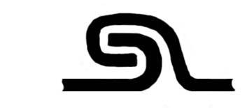
Hot rolled sections provide and excellent interlock seal, that works well against water seepage through the interlock. A ball and socket type interlock is common for hot rolled section, and this interlock is durable, and ideal for repeated use. See Figure 704-4, left, for the ball and socket type interlock. Hot rolled sections are typically more expensive, and thus, not used as frequently by contractors for temporary left in place applications.
Cold rolled sections are more common for temporary left in place applications due the fact they can be cut to any length or quantity, and are less expensive to produce than hot rolled sections. A hook and grip type interlock is common for cold rolled sections, which are known for allowing seepage through the interlock, and may become brittle over time due to the cold forming process.
See Figure 704-5, right, for the hook and grip type interlock. Pay close attention to interlocks getting jammed easily from soil, and water seepage in their final position.
Construction
Design and Approval Process
All steel sheet piling designs are done in accordance with the AASHTO Standard Specification for Highway Bridges, 17th edition, the MDOT Bridge Design Manual, and the specifics as shown in the contract plans and specifications.
Permanent steel sheet piling details are included in the contract plans, and should have a familiar look and feel with respect to the MDOT plan format. Typically these designs are completed, or approved by Geotechnical Services prior to inclusion in the final plans. The required steel sheet piling sections, embedment depths and section, elevations, and material grades will be shown on the contract plans and specifications.
Temporary steel sheet piling, and cofferdams will be conceptually shown on the plans with respect to rough plan and section views, but this is for bidding purposes only, and not based on any detailed analysis and design. The Contractor is responsible for the design of the temporary steel sheeting and cofferdam installations based on the substructure size and staging requirements, and the soil borings, and other geotechnical information as shown in the contract plans and specifications.
At locations where the combined depth of retained water or soil is less than 6 feet, the Contractor is to submit the temporary steel sheeting piling, and cofferdam working drawings for approval by a licensed Engineer per subsection 104.02 of the Standard Specifications for Construction.
At locations where the combined depth of retained water or soil is greater than 6 feet, the Contractor is to submit the temporary steel sheeting piling, and cofferdam working drawings and design calculations for approval per subsection 104.02 of the Standard Specifications for Construction.
The MDOT Geotechnical Services Section and Bridge Field Services areas will review the temporary steel sheet piling and cofferdam designs for conformance to the appropriate geotechnical and structural requirements. When reviewing the Contractor’s temporary steel sheet piling and cofferdam working drawings and calculations, the following must be shown:
- Steel sheet piling section modulus – must be at least 18.1 in3/ft of wall when adjacent to traffic
- Design methodology for bracing, struts, walers, welded or bolted connections, and other structural components, i.e. AISC Allowable Stress, AISC LRFD, etc.
- Design methodology for tie backs, deadmen, ground anchors, or other externally applied anchor supports, i.e. FHWA Publication No. FHWA-IF-99-015 (Geotechnical Engineering Circular No. 4, Ground Anchors and Anchored System)
- Embedment depths, toe information, and depth of earth retained
- Material grade of steel for all structural members
- Other than the anticipated earth pressures and the 360 psf live load surcharge (when stage line is adjacent to traffic), consideration of any temporary loads such as construction equipment, anticipated material stockpiles, and unbalanced hydrostatic pressures
- Overall plan view or temporary steel sheet piling and cofferdam installations documenting each stage of construction, with profile and cross section views to ensure all load cases are accounted for, and the system can be built as intended
Working drawings for temporary steel sheet piling and cofferdams will typically not follow the MDOT plan format, as they are developed by the Contractor. Take the time to review and understand the following important elements:
- Overall staging scheme, and locations of stage line sheeting
- Step by step sequence of construction for each stage
- Toe elevations per stage
- Waler and bracing elevations per stage
- Shelfing requirements during excavation
- Equipment or stockpiled material placement
Once the Contractor’s design is approved, ensure it is built according to the approved design. Any variations, material or section substitutions, or changes in loading or site conditions will require further review by MDOT Geotechnical Services Section and Bridge Field Services. If there are questions at any time during the temporary steel sheet piling and cofferdam installation, please contact Geotechnical Services Section or Bridge Field Services for assistance.
Driving Steel Sheet Piles
Unless prohibited otherwise on the plans, there are two methods for driving steel sheet piling, diesel impact (or drop hammers), and vibratory.
Diesel Impact (Drop) Hammers
Diesel impact or drop hammers consist of a lead mounted short stroke heavy ram, with a drive cap to fit on to the steel sheet piling shape. Steel sheet piling is driven via impact force from the ram. See Figure 704-2 for a typical impact hammer set up.
Vibratory Hammers
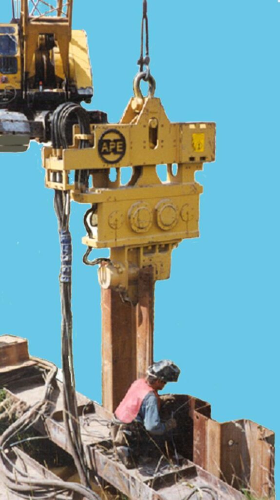
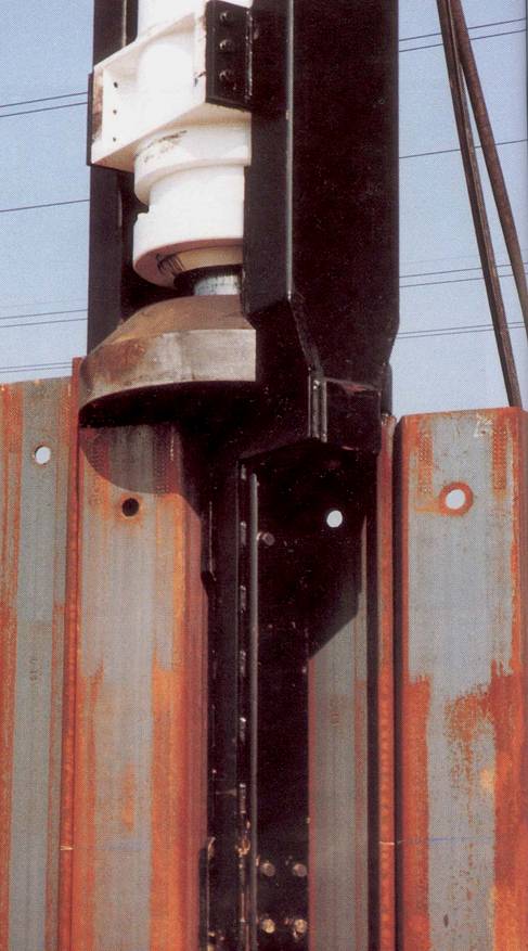
Vibratory hammers consist of a suppressor unit used to transfer energy to the gearbox, and a clamp device to hold the steel sheet pile in place for driving. Vibratory hammers allow for easy driving in sands and soft clays, but may be prohibited in the vicinity of utilities, and other structures that may suffer damage due to the vibrations. See Figure 3 for a typical vibratory hammer setup.
Permanent Steel Sheet Piling (Construction)
For permanent steel sheet piling, ensure the appropriate hammer is being used, and note if vibratory hammers are prohibited based on plan notes or project specifications. Contact the MDOT Geotechnical Services Section area for a drivability analysis if required.
Check the plans to see if permanent steel sheet piling is required to be hot dipped galvanized, and ensure the steel sheet piling sections brought to the site meet this requirement.
Ensure the steel sheet piling sections are plumb prior to driving, and are driven at the locations shown on the plans. Ensure the proposed substructure footings aligns with the inside face of sheeting.
Ensure subsequent sheets are interlocked to the already driven sheet prior to driving. Steel sheet piling sections have different interlocks depending of they are cold rolled, or hot rolled. For permanent steel sheet piling, removal is not required; however, check the plans for any cut off elevations once the footings are cast.
Lateral limits of open-ended permanent steel sheet piling also include the limits beyond the required excavation. A 1V:1H slope from the bottom of the excavation to the existing ground is typically used.
Mill Test certifications and Buy America certifications are required for all permanent steel sheet piling.
Temporary Steel Sheet Piling – Temporary Steel Sheet Piling Left In Place (Construction)
Ensure all structural materials required to construct temporary steel sheet piling meets or exceeds the material requirements as specified in the Contractor’s design. The following should be checked at a minimum:
- Steel sheet piling size designation and section modulus – i.e. PZ-22 or greater (section modulus must be at least 18.1 in3/ft of wall)
- Size and designation of any other structural components, such as bracing, struts or walers – typically HP or W shapes
- Material grade of steel – AASHTO M 270 Grade 36 (A36), Grade 50, or Grade 50W as required in subsection 906.06.B of the Standard Specifications for Construction
- Welded connections – typically fillet welds are used to connect bracings and other structural members to the steel sheet piling, with 1/4” being the minimum weld size required per table 707-1 of the Standard Specifications for Construction
Ensure the Contractor has provided new or used continuous interlock type steel sheet piling including connection and corner pieces. Used steel sheet piling must be in good condition, and its use must be approved by the Engineer prior to driving.
For temporary steel sheet piling, ensure the appropriate hammer is being used, and note if vibratory hammers are prohibited based on plan notes or project specifications. Check to ensure the hammer being used was approved for use by the MDOT Geotechnical Services area based on the drivability analysis.
Ensure the steel sheet piling sections are plumb prior to driving, and are driven at the locations shown on the Contractor’s plans. Ensure the driving line is 1’-6” outside the footing outline or at the edge of the tremie seal. Do not allow the Contractor to re-strike, or drive steel sheet piling to a greater depth once concrete is cast adjacent to sheeting sections. The top of the permanent sheeting is to be removed by cutting after placing adjoining concrete. The maximum deflection allowed at the top of the steel sheet piling is 2” where adjacent to traffic. Frequently check the behavior of the wall under earth pressures, and notify the Engineer if excessive deflections are present. See Figure 704-6 for an example of excessive deflection at the top of the steel sheet piling.
Check the plans for the temporary steel sheeting cut off elevations, and ensure the sheeting is cut off to these elevations. Do not allow the Contractor to pull up the sheeting, cut off, and then re-drive. This is prohibited per subsection 704.03.B of the Standard Specifications for Construction
MIOSHA requires the Contractor to keep a copy of the temporary sheet piling design on site during construction at all times. Ensure the working drawings for the approved temporary steel sheeting design are on site and being followed.
Lateral limits of open-ended temporary steel sheet piling also include the limits beyond the required excavation. A 1V:1H slope from the bottom of the excavation to the existing ground is typically used.
Mill Test certifications and Buy America certifications are required for all temporary steel sheet piling left in place. General certifications are required for temporary steel sheet piling. General certifications can be in the form of manufacturer’s catalog cuts identifying the sections being used.
Cofferdams – Cofferdams Left In Place(Construction)
Ensure all structural materials required to construct temporary steel sheet piling meets or exceeds the material requirements as specified in the Contractor’s design plans. The following should be checked at a minimum:
- Steel sheet piling size designation and section modulus – i.e. PZ-22 or greater (section modulus must be at least 18.1 in3/ft of wall)
- Size, span lengths and designation of any other structural components, such as bracing, struts or walers – typically HP or W shapes
- Type of tie-back or ground anchor, if any, and testing requirements for lock off forces
- Material grade of steel – AASHTO M 270 Grade 36 (A36), Grade 50, or Grade 50W as required in subsection 906.06.B of the Standard Specifications for Construction
- Welded connections – typically fillet welds are used to connect bracings and other structural members to the steel sheet piling, with 1/4″ being the minimum weld size required per table 707-1 of the Standard Specifications for Construction* Weld electrode of E70XX
- Top of sheeting elevations, embedment depths or refusal elevations, and bracing elevations
- Plan, section and elevation details for each stage
- Construction sequence as it relates to driving steel sheet piling, bracing, and allowable excavation limits and elevations
- Partial or total enclosure contains interior clearance sufficient for constructing forms, and providing a safe working area
Ensure the Contractor is constructing the cofferdam elements using the MDOT approved design plans, as it is common for Contractor cofferdam designs to go through many revisions prior to final approval.
To track critical cofferdam installation items, use MDOT form 1990, titled “COFFERDAM INSTALLATION, PILING PLACEMENT, AND TREMIE POUR INSPECTOR’S CHECKLIST”. Cofferdams are typically constructed around a template made of HP or W sections, or welded steel tube piling which serves as bracing when the enclosed area is dewatered. Cofferdams must conform to all conditions included in the Michigan Department of Environment, Great Lakes, and Energy (EGLE) or other project permits. The Contractor must obtain permission to deviate from the plans or approved permits.
The Contractor must secure an approval for his method of construction from EGLE in water crossing situations for alternate designs from project plans. A well point system may be used on land to control ground water. It cannot be used in waterways because it causes siltation.
It should be constructed so that it does not hinder navigation or the river flow.
Ensure the Contractor has provided new or used continuous interlock type steel sheet piling including connection and corner pieces. Used steel sheet piling must be in good condition, and its use must be approved by the Engineer prior to driving. Ensure all other structural elements such as bracing, walers and struts are in good condition, free of significant section loss, large holes or other defects. Minor rusting and/or section loss is acceptable, as most contractors re-use these elements from project to project. If there are any questions regarding the condition of structural elements to be used, please contact Bridge Field Services for support.
For steel sheet piling installation, ensure the appropriate hammer is being used, and note if vibratory hammers are prohibited based on plan notes or project specifications. Check to ensure the hammer being used was approved for use by the MDOT Geotechnical Services Section area based on the drivability analysis.
Ensure the steel sheet piling sections are plumb prior to driving, and are driven at the locations shown on the Contractor’s plans. Out-of-plumb steel sheet piling installation leads to many problems, particularly at the corners.
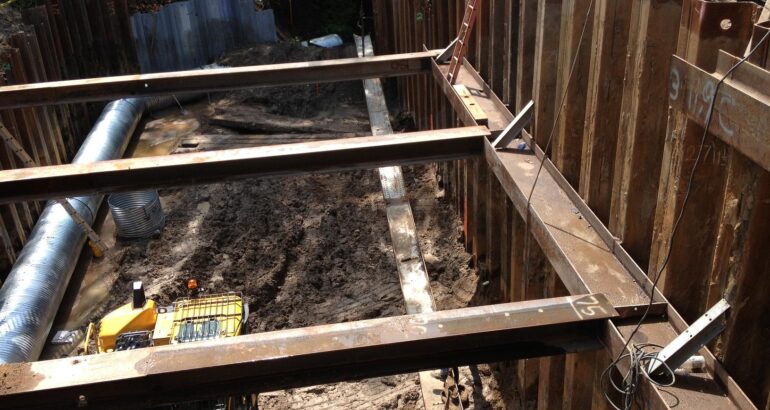
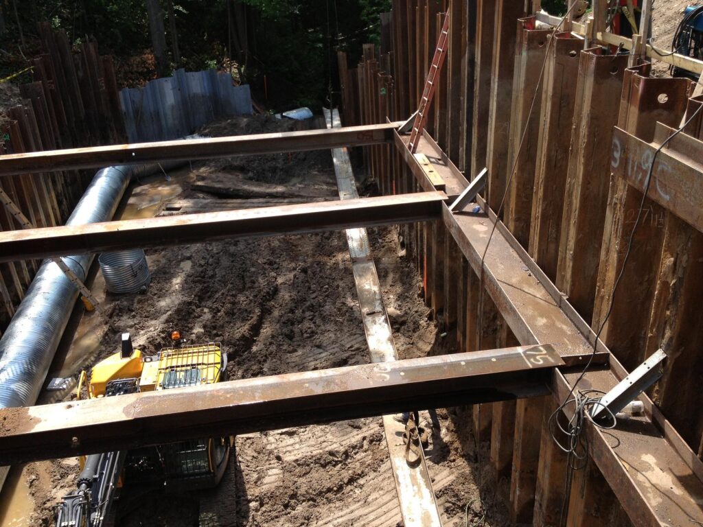
Bracing, walers and struts should be installed at the elevations shown on the Contractor’s plans as soon as practicable. Do not allow the Contractor to advance the excavation or drive steel sheet piling further than the maximum unbraced lengths. See Figures 704-7 and 704-8 for cofferdam bracing using walers and struts.
Ensure structural elements such as bracing, walers or struts are attached to the sheeting and each other with good quality welds, per the MDOT Field Manual for Pile Welding. The Contractor is prohibited from attaching structural elements to the substructure forms. Bracing may be temporarily attached to finished concrete substructure elements given the staging requirements. Ensure all bracing and connections are removed from the finished concrete substructure elements when the overall cofferdam is removed.
When inspecting cofferdam elements, ensure the Contractor provides tie off points for fall protection around the cofferdam. Life jackets are required when inspecting cofferdam elements prior to dewatering.
MIOSHA requires the Contractor to keep a copy of the cofferdam design on site during construction at all times. Ensure the working drawings for the approved temporary steel sheeting design are on site and being followed.
Mill Test certifications and Buy America certifications are required for all cofferdams left in place. General certifications are required for cofferdams. General certifications can be in the form of manufacturer’s catalog cuts identifying the sections being used.
Obstructions are to be removed per subsection 718.03.F.2 of the Standard Specifications for Construction. Obstructions may include old concrete foundations, abandoned utilities, or boulders and cobbles. Ensure the Contractor uses tools and procedures as approved by the Geotechnical Services Section area to remove the obstructions. Special procedures and tools include:
- Chisels
- Boulder breakers
- Core barrels
- Air tools
- Hand excavation
- Temporary casing
- Enlarging the drilled shaft diameter
Removal of obstructions that require special equipment or tools will be measured and paid for as extra work per subsection 718.04.D of the Standard Specifications or Construction. A budget amount will be established to pay for removing obstructions. If the Contractor and the Engineer cannot agree on a lump sum price, the Engineer will direct the work to be done on a force account basis.
Place tremie concrete under water in accordance with subsection 706.03.H.3 of the Standard Specifications for Construction.
Immediately prior to placing the permanent foundation piling, check to make sure the bottom of tremie is excavated to the elevations shown on the plans using probes in a grid pattern. To help ensure a water tight seal, ensure the steel sheet piling corrugations are cleaned to the full depth of the excavation.
Prior to pouring the tremie concrete, ensure that the water level inside the cofferdam is equal to, or greater than the water outside the cofferdam.
During the tremie concrete pour, take all concrete QA/QC samples from the truck; do not remove the tremie tube from the fresh concrete to obtain the concrete samples.
Ensure the Contractor is checking the grade on the tremie pour. Concrete is to be placed to at least the elevation of the top of tremie seal as shown on the plans, but no more than +6 inches above the tremie seal.
Ensure the tremie tube is always kept in the freshly deposited concrete; only withdraw the tremie upon completion of each pour, or as required to place concrete around cofferdam bracing. Ensure the Contractor pumps off any displaced water in the cofferdam during the tremie pour into a geotextile filter bag, per subsection 704.03.C of the Standard Specifications for Construction. Displaced water within the cofferdam cannot overtop the steel sheet piling. Do not pump water below the water level at the start of the pour.
Ensure the concrete has attained at least 50 percent of the 28-day compressive strength, or after test beams break with a modulus of rupture of at least 325 psi.
Dewater the cofferdam by pumping water through a geotextile filter bag, per 704.03.C of the Standard Specifications for Construction. The Engineer may allow pumping of the water directly into the water course, if the cofferdam water is determined to be silt-free and sediment-free.
Water leakage through sheeting joints is common, but can usually be stopped by dropping fine cinders into the water outside the cofferdam where the leakage is occurring. The cinders will plug the joints and stop, or at least materially reduce, the water flow into the cofferdam.
Should leaking between interlocks, or between steel sheet piling and tremie seal affect the ability to construct the substructure elements in the dry, contact MDOT Geotechnical Services area for options on sealing the cofferdam. If the Contractor’s operation is suspect of water pollution or siltation, the Engineer will ask for a Michigan Department of Environment, Great Lakes, and Energy (EGLE) inspection as provided by Section 107 of the Standard Specifications for Construction.
Upon completion of the substructure element construction, ensure the cofferdams are removed without disturbing, or marring finished concrete.
If portions of the cofferdams are to be left in place, ensure steel sheet piling is cut off to the elevations shown on the plans. Do not allow the Contractor to pull up or re-drive cofferdam sheeting to match the cut off elevation unless otherwise shown on the plans, or approved by the Engineer.


