From cargo loading to unloading, from pile driving to jetty building, lifting is an essential component of the marine construction workflow. Slings are an integral part of lifting. The following guide to safe usage of slings is compiled from industry sources and government publications.
Slings shall have a minimum design factor appropriate to the type of material as specified in the appropriate section. Features that affect the rated capacity of the sling and that shall be considered in calculating the design factor are:
- a. Nominal breaking strength of material from which it is constructed.
- b. Splicing or end-attachment.
- c. Number of parts in the sling
- d. Type of hitch (e.g., straight pull, choker hitch, or basket hitch).
- e. Angle of loading and load center of gravity.
- f. Diameter of curvature around which the sling is bent.
The center of gravity of an object is a point around which the entire weight may be concentrated. To make a level lift, the crane hook or point of suspension must be directly above this point. While slight variations are usually permissible, if the crane hook is too far to one side of the center of gravity, dangerous tilting will result and should be corrected at once. For this reason, when the center of gravity is closer to one point of the sling attachment than to the other, the slings must be of unequal length. Sling stresses and sling angles will also be unequal (see Figure 1).
Rigging shall be configured such that slings do not reeve or slip through the hook. To attach the load, locate the center of gravity, position the crane hook directly above the center of gravity, and then rig the load so that it will lift level and true.
Load Angle Factor
The following is an example of selecting a sling using the load angle factors shown in Figure 1.
Load = 1,000 lb.
Sling = 2-legged bridle.
Angle with horizontal = 45 degrees.
Load angle factor from Figure 11-7 = 1.414
Each of the two legs would lift 500 pounds if a vertical lift were made. However, there is a 45 degrees sling angle involved. Therefore, the 500-pound load would be multiplied by the load- angle factor in the chart, giving a total of 707 pounds (500 pounds x 1.414) tension in each sling leg. Each sling leg, therefore, must have a rated capacity of at least 707 pounds.
Safe Load
The rated capacity or working load limit (WLL) of a sling varies depending on the type of hitch. The rated capacity tables in this section show the applications for which the various safe loads apply when the slings are new. All ratings are in pounds.
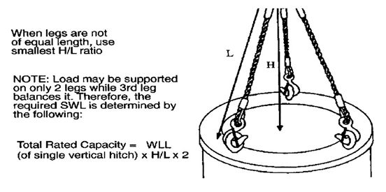
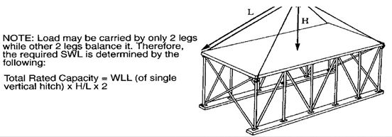
Figure 2 provides information for determining the total rated capacity of three-leg slings so as not to introduce a working load in direct tension in any leg greater than that permitted. Two legs should be considered to carry the load because in normal lifting practice, the load will not be uniformly distributed on all legs. If rigging techniques, verified by a qualified rigger, ensure that the load is evenly distributed then full use of three legs is allowed. Special rigging techniques verified by a qualified engineer shall be required to prove that a load is evenly distributed over four or more sling legs.
Design Factor
In general, a design factor of 5:1 is maintained throughout this section with the exception of alloy steel chain slings. Also, certain sling fittings, such as hooks (which will deform beyond usefulness before breaking) cannot be assigned a definite numerical design factor. In such cases, suitable safe loads are listed, based on wide experience and sound engineering practice.
Sling Care
Proper care and usage are essential for maximum service and safety. Wire-rope slings shall be protected from sharp bends and cutting edges by means of corner saddles, burlap padding, or wood blocking. Overloading shall be avoided, as shall sudden dynamic loading that can build up a momentary overload sufficient to break the sling.
Sling Storage
Personnel using slings shall ensure that they are stored properly as follows:
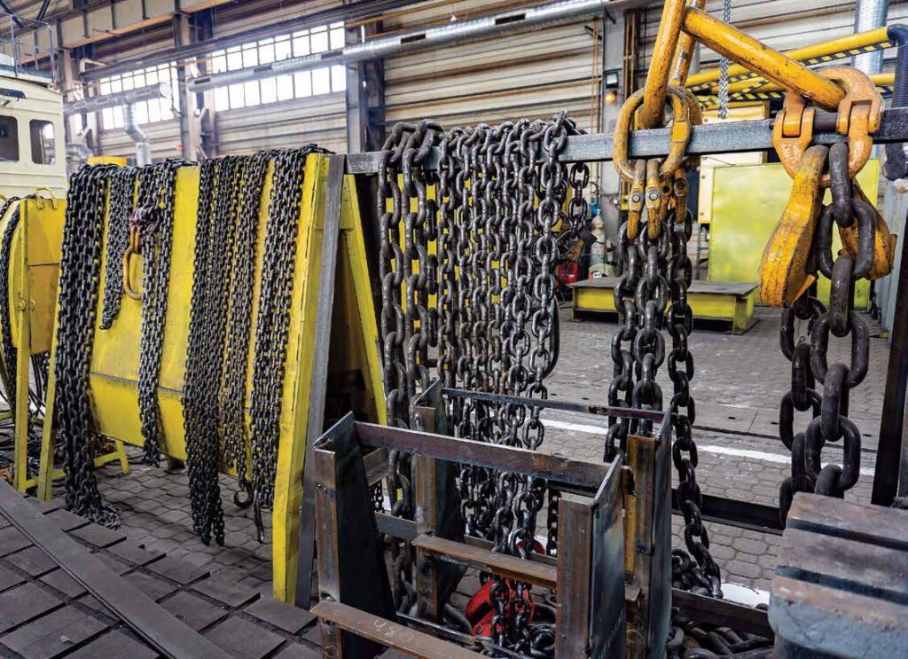
a. Slings should be stored in racks (preferably vertical) and in designated locations when not in use. Do not store slings in a location where they will be subjected to mechanical damage, corrosive action, moisture, extreme heat, or kinking. Slings may require segregated storage as determined on a case- by-case basis.
b. Before storage and periodically during storage, wipe slings clean to remove as much dirt and abrasive grit as possible and re-lubricate wire rope and chain slings to extend their useful life. Chains should not be lubricated when in use.
c. Do not store metal-mesh slings in areas where the temperature exceeds 550 degrees F (288 degrees C) or 200 degrees F (93 degrees C) if elastomer covered.
d. Do not store synthetic-web slings where the temperature exceeds 200 degrees F (93 degrees C).
Inspections
a. Sling users shall visually inspect all slings each day they are used or prior to use if the sling has not been in regular service (records are not required). In addition, a periodic inspection shall be made at least annually by a qualified inspector. More frequent intervals for periodic inspections should be established if necessary as determined by a qualified person based upon:
- Frequency of sling use.
- Severity of service conditions.
- Nature of lifts being made.
- Experience gained on the service life of slings used in similar circumstances.
b. Users shall carefully note any deterioration that could result in an appreciable loss of original strength and determine whether further use of the sling would constitute a safety hazard. Removal from service criteria are provided for each type of sling in their respective sections.
Sling Periodic Inspection Records
Individual site programs shall describe how inspections are recorded. These records may include an external coded mark on the individual sling tag (e.g. date, annually changed color stripe, etc.) indicating both periodicity and the satisfactory completion of the required inspection, or a written record as acceptable documentation.
WIRE-ROPE SLINGS
a. In general, wire-rope slings are made up of 6 x 19 or 6 x 37 classification wire rope. Rotation- resistant wire rope shall not be used for wirerope slings. Different kinds of slings have been developed for specific purposes. These are divided into different groups or types as follows:
- Endless-loop slings (grommet construction) and single-part slings with single-rope legs, double-rope legs, or multiple-part rope legs.
- Two-leg bridle slings with single-rope legs, equalizing double-rope legs, or multiple-part rope legs.
- Three-leg bridle slings.
- Four-leg bridle slings.
- Special slings and combinations.
b. The total load that can be safely lifted with slings depends on the rating of the slings and the manner in which they are attached to the load.
c. Braided slings are made by braiding ordinary wire ropes together, thus making them more flexible than wire-rope slings. The size of a braided sling is determined by the diameter of one wire rope and the number of ropes in the cross section of the slings.
d. The design factor for wire-rope slings shall be a minimum of 5:1 based upon breaking strength.
e. When a wire rope sling is used in a choker hitch, the normal angle formed in the rope body as it passes through the choking eye is 120 degrees or greater. Do not confuse the choke angle with the angle of inclination of the load. In Table 1, rated load in load capacity is for angles of 120 degrees or greater. For smaller angles, reduce the rated load to the percentages given.
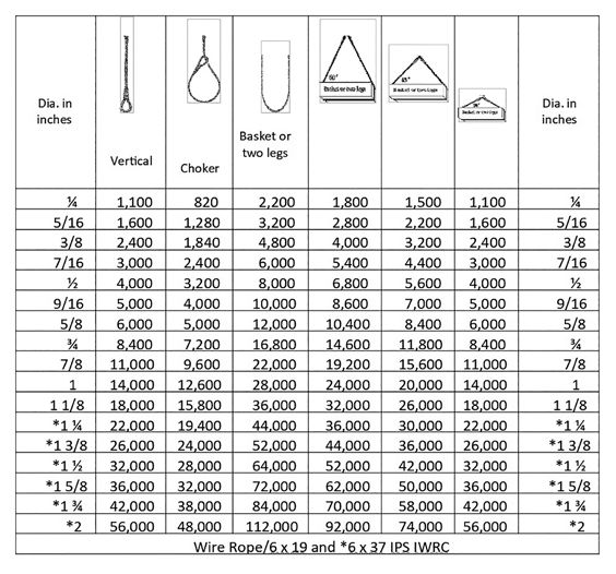
Note: These values only apply when the D/d ratio is 25 or greater (choker and basket hitches). D = Diameter of curvature around which the body of the sling is bent d = Diameter of rope. Choker hitch values apply only to choke angles greater than 120 degrees
Removal from Service Criteria
a. Wire rope slings shall be immediately removed from service if any of the following conditions are present:
- Missing or illegible sling identification
- Broken wires
- For strand-laid and single-part slings, 10 randomly distributed broken wires in one rope lay, or five broken wires in one strand in one rope lay.
- For cable-laid slings, 20 broken wires per lay.
- For six-part braided slings, 20 broken wires per braid.
- For eight-part braided slings, 40 broken wires per braid
- Severe localized abrasion or scraping
- Kinking, crushing, bird caging, or any other damage resulting in damage to the rope structure
- Evidence of heat damage
- End attachments that are cracked, deformed, or worn to the extent that the strength of the sling is substantially affected
- Severe corrosion of the rope, end attachments, or fittings
- Other conditions, including visible damage, that cause doubt as to the continued use of the sling
Proof-Testing
a. All swaged socket and poured socket sling assemblies shall be proof-tested to the wire rope or fitting manufacturer’s recommendations but in no case greater than 50 percent of the component wire rope’s or structural strand’s nominal strength. All other sling assemblies shall be proof-tested when specified by the purchaser.
b. As a minimum, the proof load shall be equal to the rated capacity but shall not exceed:
- 125 percent of the vertical rated capacity for single-let, hand-tucked slings.
- 200 percent of the vertical rated capacity for mechanical-splice single-leg slings and endless slings.
c. The proof-load for multiple-leg bridle slings assemblies shall be applied to the individual leg and shall be in accordance with paragraphs a. and b. as applicable.
d. Master links to which multiple-leg slings are connected shall be proof-loaded to 200 percent times the force applied by the combined legs.
e. Welded end attachments shall not be used unless proof-tested at 2 times rated capacity prior to initial use.
f. Test loads described above shall be accurate to within –5 percent, +0 percent of stipulated values. A written letter of certification by the manufacturer or a pull test witnessed and certified in writing by a qualified person is acceptable.
Republished from Marine Construction Magazine Issue V, 2022


